First 210
Home
Tech Notes
Index
|
Beneteau First 210 Tech Notes
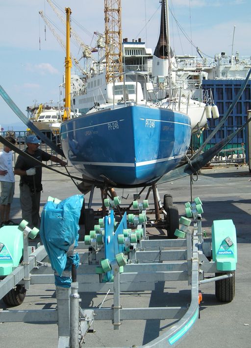
In the attachment I am sending you some pictures of this summer campaign (removing the keel) on my F210, Ursa Minor, #126. Let me first briefly explain the circumstances that lead us to finally do all this work:
Initial plan was to fix the hull osmosis, inherited from the former owner. The whole gel-coat (approx. top 5mm) on the under-water area was removed right to the laminate. Along with it subsequent red-ish filler-like layer that decreases transparency of the boat hull was also removed. Since the boat was on a high cradle already we decided to take the opportunity to remove the keel and replace all the bushings (nylon parts). Parts were purchased via Beneteau dealer in Slovenia (ordered from Beneteau France). There should be no problem to get the whole set still.
I will try to explain the major steps as done using the name/number of adequate picture.
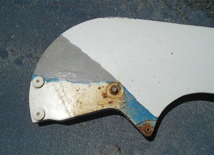
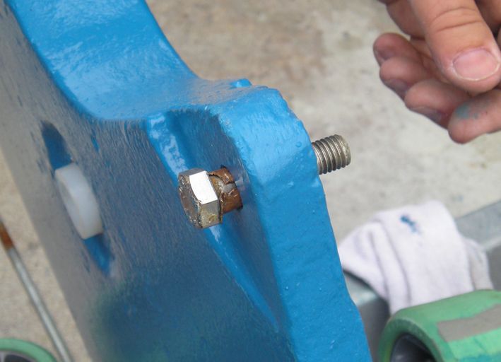
No 1 That's how the keel raising mechanism (a pin that holds the keel) looked like after 10 years in fresh water (Lac-Leman, France) and two summer seasons on the Adriatic sea. It was also the first screw that was removed.
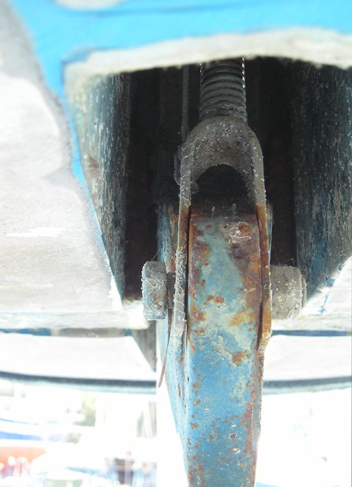
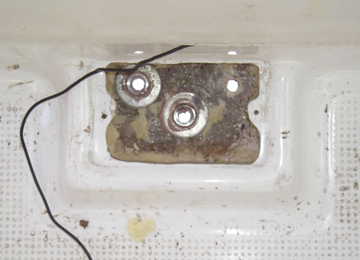
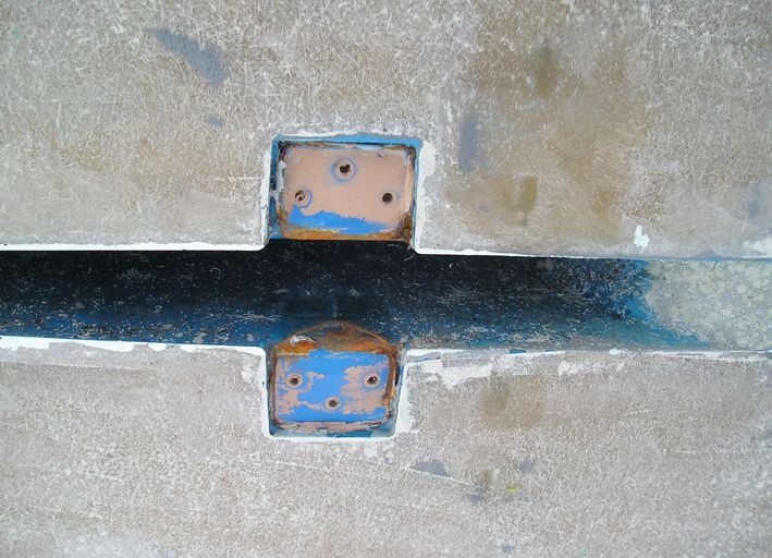
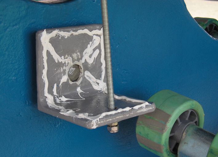
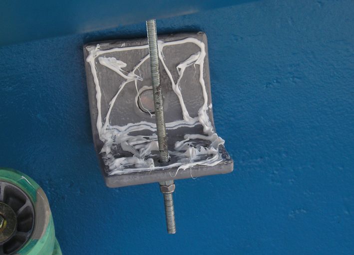
No 1.1, 2, and 3 In order to remove the keel, the raising mechanism was fully removed and both axle holders unscrewed. Axle is hold by two, L-shaped metal plates that are fixed on a hull with three screws each on each side of the keel. That's also all that holds the keel really When in their place, screws with nuts can be seen inside the boat under white laminate plates on the floor on each side of the keel cassette. Before unscrewing the nuts inside the boat (picture 1.1), the keel has to be fixed in order to keep it in balance. On the contrary, keel can drop down from its place, damaging the hull or (even worse) somebody on its way. Between each axle holder and the keel a nylon spacer is placed on the axle to keep the constant distance from boats hull (picture 3). Note! Six holes for axle holder screws are theoretically the only place when you can get water inside the boat. It is that for important to use some kind of sealant. My experience; factory sealer was so strong that it held the entire keel (300kg) still after all the screws were fully removed. Some "help" was needed to get it down finally.
No 4 The "head" of the removed keel. You can see two white, nylon discs (two on each side). When the keel is on its place these discs prevent the keel to swing sideways. They act as an additional support against cassette's inner walls, making the keel firm when extended. At least theoretically that should be their role. My experience; the axle is almost impossible to fix as firmly that the keel would not have some sideway space. The discs can be however lined in order to get tighter fit with keel cassette. I believe somebody already rote about this problem on these pages. My concern here remains; to what extend can such measure effect the smoothness of raising mechanism operation? (I used factory recommended discs alone).
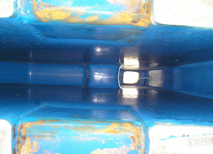
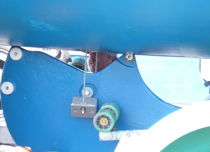
No 5,6 Keel cassette after the raising mechanism and the keel have been removed and inside was cleaned.
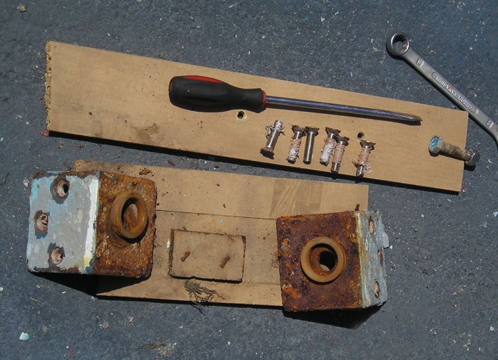
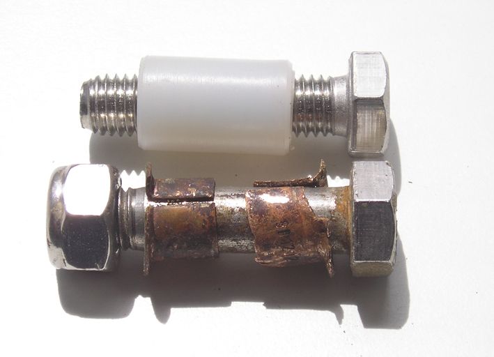
No 7, 8 Important! The nylon bushing that comes with a Beneteau replacement set is too big and can not be fitted into a F210 keel. Obviously for existing f211/21.7 models some adjustments were made. The old, brass ones, were that for used again (picture 8). Take care while removing them! They can break easily!
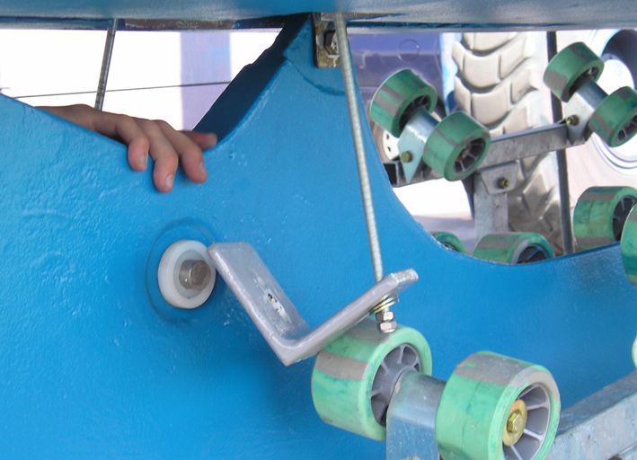
No 9, 10, 11 Before refit, the side discs on the keel's "head", the axle and both side axle spacers were replaced. The axle holders were grinded and repainted. The keel was placed on the boat's trailer in order to have the upright position and best support possible. The boat was brought over it with (picture 9) and lowered almost to the keel. The raising mechanism was first refit (picture 7, 8). The long coiled rods were used and placed in the middle holes on each side of the cassette (axle holders with nuts on the bottom). The axle holders were placed on the axle and the whole keel was slowly risen up in its place (approx. 30cm). Original length screws were used in to fully tighten the keel. The coiled rods were finally removed and also replaced with adequate short screws. Sika-flex 292 was used under the holders and around the screws (also on the cabin side under the nuts) to properly seal all the holes.
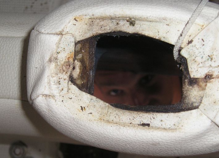
Before put to the water, make sure that the top of the keel cassette (picture 5) is properly sealed/fabrics in its place otherwise it can happen that water will find its way into the cabin when the waves were high.
Hope this helps. I am sorry for all the spelling mistakes I migt have done...
With best regards
Tomaz Vernik
updated January 22, 2006
|