Beneteau First 211 Tech Notes
Title: Keel Lift Bearing for the First 211
Author: Mike Beasley
KEEL LIFT JACK SERVICING ON A BENETEAU FIRST 211
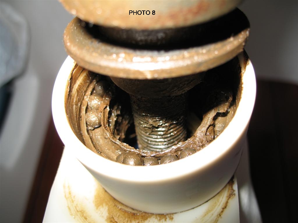
The bearing on my 211 failed. This became apparent after going aground when the jack mechanism rose up above the casing and some ball bearings were ejected onto the cabin floor. It appeared that the metal cage containing the balls got screwed up somehow. (See Photo 8). I do not believe that going aground caused this failure because the design of the jack is clever in that it simply rides up when the keel is pushed up and should come to no harm. I suspect that the bearing was already damaged before I went aground because the feel of the lift mechanism was always a bit rough compared to after I fitted the new bearing when it is now beautifully smooth. I think there is more likelihood of damage to the bearing after going aground when the keel drops down again when the bearing might not be ‘square’ relative to it’s seating so the whole weight of the keel is taken by one side of the bearing. As I am the second owner I am not sure of the boat’s previous history.
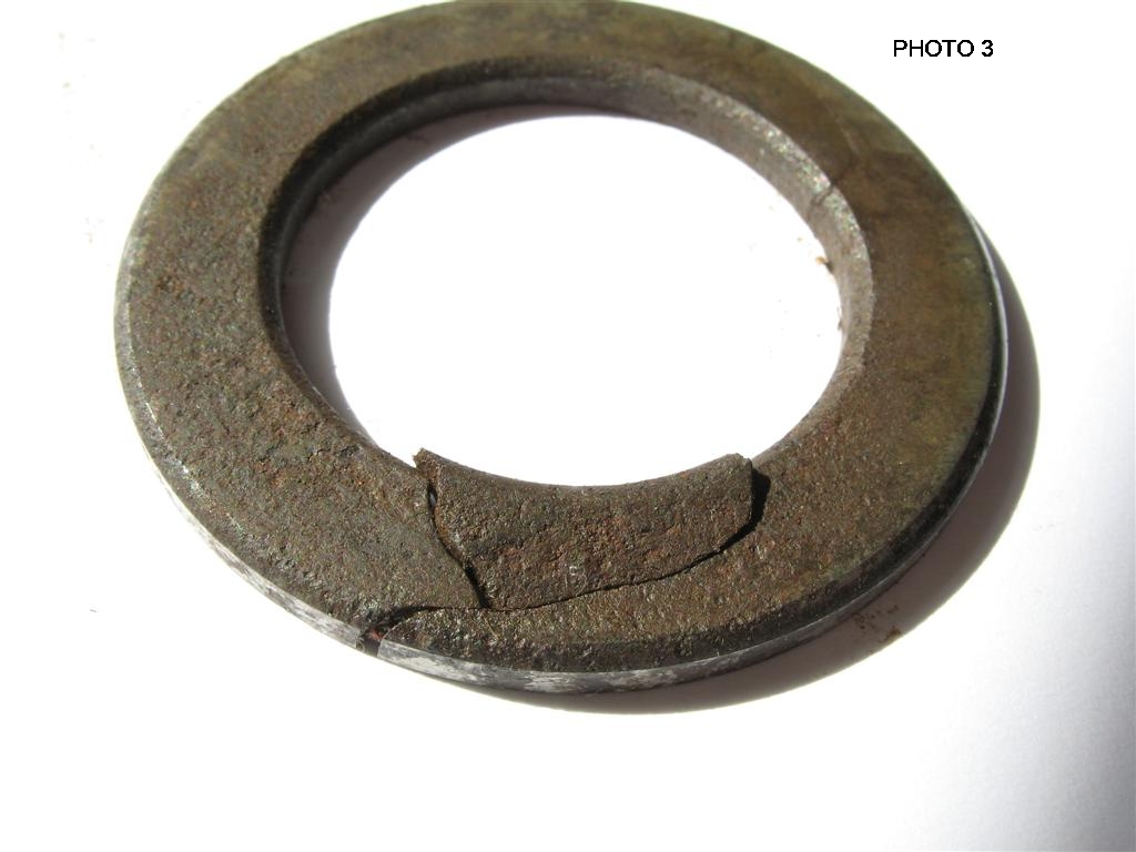
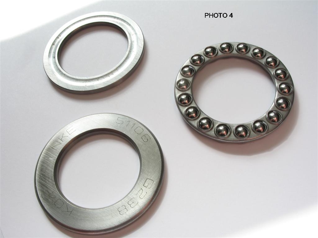
An alternative explanation might be simply a faulty bearing. The bearing is made up of 18 balls in a cage in-between two seats, the balls run in grooves in the two seats, the outer side of each seat being flat. Photo 4 shows the three components of a new bearing. In Photo 3 it can be seen that the upper seat of my bearing was found to be fractured - this could have been due to a fault in the manufacture of the seating.
This is the procedure for replacing the bearing and also the bronze nut if required. My boat is 3 years old and not trailered so the keel is always left down and so I found no wear in the bronze nut and did not replace it.
NOTE the following applies to a 211. I think the jack on the 210 is of a slightly different design and cannot be unscrewed and withdrawn into the cabin. If you have a 210 and try this you may damage the jack. (Ed: My 210 is definitely different - the threaded rod is attached to the lower part of the jack and you have to put the boat in a lift to service the jack.)
- Assuming you start with the boat in the water and the keel raised, lower the keel fully by turning the handle 57 turns anticlockwise. Continue turning the handle about another 12 turns. You will feel a little resistance at first then it becomes free.
- The jack has now separated from the what I will call the keel-tube. The latter is forked at the lower end and attached to the keel. At it’s upper end it has an external fine thread which mates with a fine internal thread in the bronze nut. Lift up the entire jack into the cabin. You will see that the bronze nut is hard up against the end of the coarse-threaded rod.
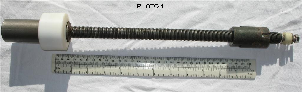
- Using the jack handle and a spanner (wrench) back off the bronze nut a few turns. See Photo 1.
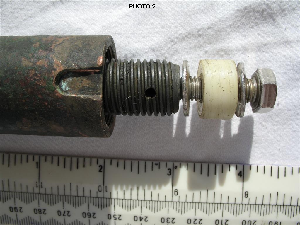
- At the end of the coarse-threaded rod you will see the thick white plastic washer located between two thin stainless steel washers all held in place by a 30mm M8 bolt in A4 stainless. I think the function of the thick washer is to prevent the end of the screwed rod from damaging the inside of the keel-tube when the jack is raised and lowered and the threaded rod passes up and down inside the keel tube. The M8 bolt is prevented from rotating as the jack turns by a 3mm roll pin inserted through the threaded jack rod into the bolt. The roll pin only goes half way into the bolt so unfortunately cannot be drifted out. Use the handle and a ring spanner to turn the bolt and break the roll pin then withdraw the bolt and washer assembly and make sure you have got rid of all the roll pin fragments. Photo 2 shows the roll pin removed and the M8 bolt in position.
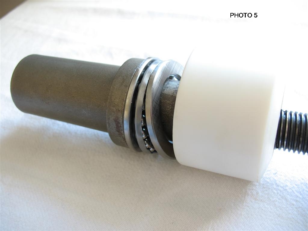
- Replace the bearing making sure the seats are the right way round ie with the grooves against the balls. Photo 5 shows the new bearing.
- Replace the bronze nut.
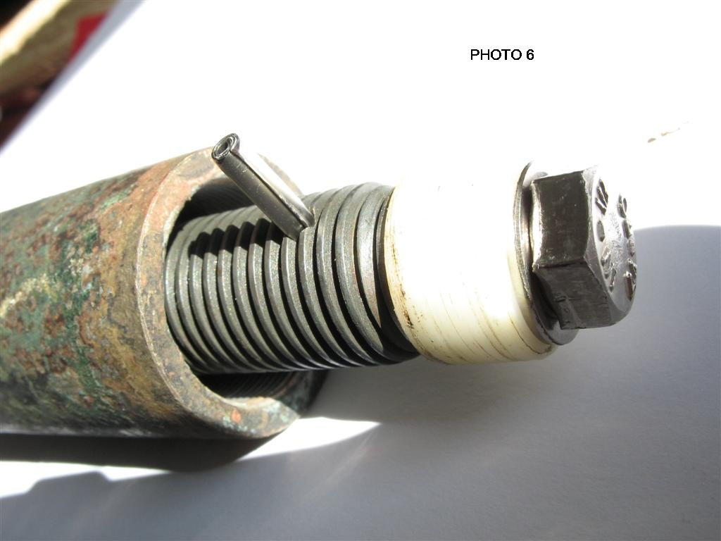
- Screw in the M8 bolt with the three washers so that the hole in the threaded jack rod is lined up with the hole in the bolt and insert the new roll pin. See Photo 6. Sharp eyed readers will see that the replacement for the roll pin is actually a spring pin. I could not obtain a 5mm long roll pin and had to make do with a 10 mm spring pin snipped down to be flush with the thread - it does the job. I also used some Loctite 577 on the M8 bolt thread just to make sure!
- You are now almost ready to reinstall the jack but three vitally important things to do. First thoroughly grease the ball bearing and the coarse thread of the jack rod with a waterproof grease. Second use the handle and spanner to tighten the bronze nut at the end of it’s run, don’t use too much force, just enough to prevent it easily turning when you try to screw the assembly back onto the threaded keel-tube. Third, put plenty of Loctite 577 up inside the bronze nut on its fine thread so as to prevent it from undoing from the keel-tube when you screw the jack home.
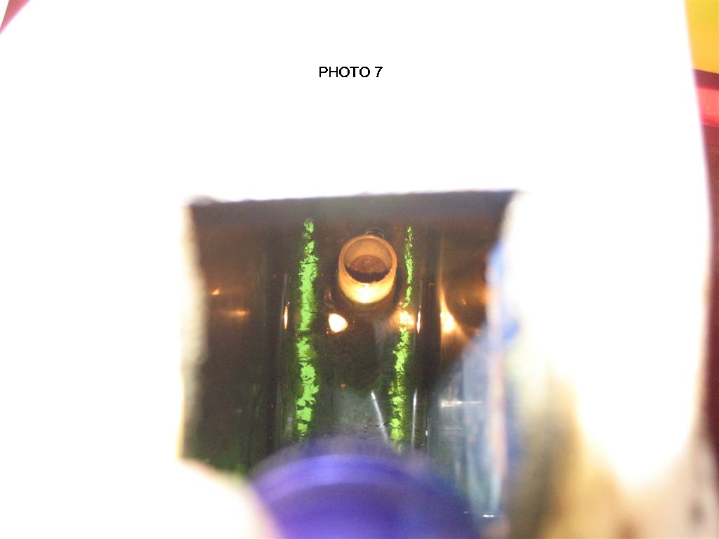
- Insert the jack assembly back down into the casing and screw it down into the keel-tube. I found this the most difficult part of the operation as the keel-tube is inclined to tilt forward so you have to locate it by wiggling the jack around and turning it clockwise eventually you will feel that it is engaged and screwing on. (Photo 7 shows what the top of the keel-tube looks like when looking down into the casing. The keel-tube is just above the level of the water, the purple object is a Maglite torch as this is a very difficult scene to light!). Once you have threaded it on you can use the jack handle to tighten it up 12-14 turns clockwise. Loctite 577 takes about 3 hours to cure so I would leave it to cure before turning the handle anti-clockwise just to make sure it doesn’t come undone (This may not really be necessary as the friction in the fine thread will be much greater than the well greased coarse thread of the jack but better safe than sorry).
A few notes and comments:-
I tried to procure a new bearing from three a Beneteau agent in the UK but no luck. Eventually I measured the bearing and realised that it was a standard size in fact a “30x47x11 thrust ball race single with 2 flat seats” ie 30mm inside diameter, 47mm outside diameter, thickness or width of 11mm. This bearing is designated a 51106 and the number is the same for all manufacturers. In fact my new bearing was made by NKE an Austrian company. The bearing supplier was Simply Bearings Limited of Warrington, England although I would guess that a 51106 is available freely worldwide. The cost was only £9.43 including post, packing and Value added Tax.
I had trouble with a source of roll or spring pins. Eventually I got some from Felix Fasteners of Alton England. Charlie Backhurst there is very helpful and carries a vast range of A4 stainless items.
You will notice from the photo of the bronze nut there is a groove in it’s lower end and also from Photo 7 that there is some sort of metal lug at the top forward edge of the keel-tube. My guess is that these lock together somehow to prevent rotation but at the same time allowing the bronze nut to be screwed to the keel tube. How this works is a mystery to me!
updated June 26, 2006
|